


SolidPlant Workflow
In SolidPlant the workflow starts with SolidPlant P&ID. In SolidPlant P&ID it is very easy to place equipment symbols, which can be scaled at the time of placing. Process lines snap to the equipment and automatically place the nozzles. Tag Members can be placed very quickly. Properties of the process line, such as size, specification and service are reflected in the drawing. Components that are placed in the line will automatically flip to the direction of flow. SolidPlant P&ID has the option to connect multiple sheets with each other. The data from SolidPlant P&ID, such as line list, nozzle list, equipment list, etc., can be synchronized to SolidPlant 3D.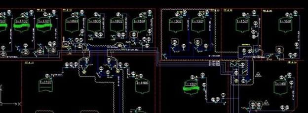
SolidPlant is driven by a database which allows the pipe specification to be picked or created by the user. Based on this specification the pipe routing will take place. SolidPlant contains a very large set of manufacturer catalogs of pipe components: valves, gaskets, elbows, flanges, bolts, etc. For example, the catalog of ANSI/ASME standards, which is presently a worldwide standard for piping works, JIS and DIN standards, and brands from various manufacturers such as Crane, Ladish, Fisher. All these and many more are ready-made, available on the go. If a user has his own existing specification, it can be easily imported into the SolidPlant Spec Creator.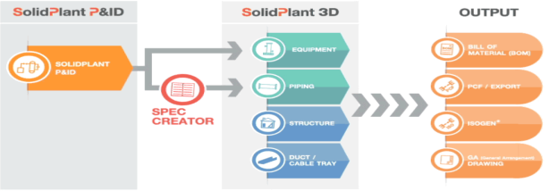
In SolidPlant 3D a structure is based on a 3D grid. The grid lines can then be transformed into 3D beams which are in accordance with official industry standards. SolidPlant 3D has prepared templates for stairs, ladders, hand railings, floorplates, trusses, walkways, platforms, pipe bridges and conveyors. All these templates can be generated from a single sketch line, after which all properties, such as dimension and position, can be specified.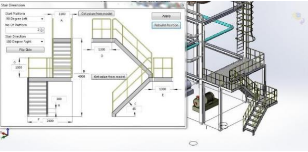
SolidPant 3D provides provides templates to create several types of typical equipment such as tanks, vessels, towers, heat exchangers and pumps. Dimensions can be easily altered and nozzle placement, based in the data from SolidPlant P&ID, to any part or area of the equipment is very user friendly. 3D models can also be imported from other CAD software, on the condition the format is readable by SolidWorks.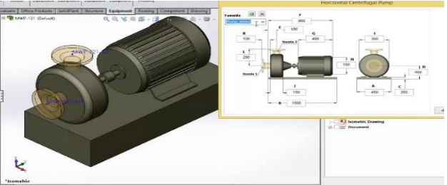
Based on the pipe component specifications selected or created in the Spec Creator, the pipe routing will take place. SolidPlant 3D offers four ways to execute the routing. In Manual Route, the most straight-forward way of routing, it’s the user who decides which way the pipe is going, and draws the routing by himself. As this would work for smaller projects, it would be very time consuming for bigger projects. For this reason, SolidPlant 3D offers Auto Route. Just by selecting the start and end nozzle, the program will automatically generate the routing, saving a lot of time. With Smart Route the data from the line list is used to select a specific route line. SolidPlant 3D will then automatically generate the routing and offers 8 route alternatives for that specific line. With the groundbreaking feature Multi Route Navigator, SolidPlant 3D can generate as many preview lines as the user wants to. These preview lines can then be transformed into the
3D models.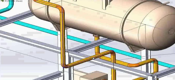
In any of the four ways of routing, components and fittings are automatically placed, based on the data from the Spec Creator. Adjustment to the pipe line comes very easily, just by dragging the line. Changing the pipe’s size will automatically change the size of the components accordingly. Placement of valves and pipe supports comes naturally. SolidPlant 3D also offers advanced piping features such as sloped pipes, stub ins, pipe jogging and pipes with insulation.
SolidPlant 3D provides two methods to model the ducting, cable trays or other non-round piping. Using the manual method, components can be placed one by one. The duct system can also be modeled by using a 3D sketch method, after which the program will generate all the components automatically.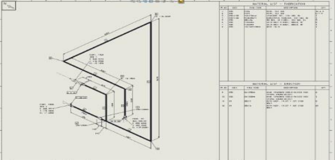
After the design of structure, equipment and piping is completed, SolidPlant 3D offers all the required output documents. SolidPlant 3D can generate the isometric drawing automatically by using the industry standard Isogen by Alias, which is embedded in SolidPlant 3D. The general arrangement drawing can also be created automatically with SolidPlant 3D’s Auto GA feature. A bill of material and PCF files are of course also available in SolidPlant 3D.